Privacy statement: Your privacy is very important to Us. Our company promises not to disclose your personal information to any external company with out your explicit permission.

1 Introduction
The semiconductor light-emitting diode (LED) light source has the characteristics of small volume, high efficiency, fast response, easy dimming, wide color gamut, no mercury pollution, long service life, etc. It is a new energy source with energy saving and environmental protection. With the continuous improvement of LED technology, especially the continuous improvement of light efficiency, it has broad application prospects in the fields of projection display, backlight source and urban lighting. However, since the spatial intensity of the LED is similar to the Lambertian type distribution, the illuminance formed on the illuminated surface is rapidly attenuated with the increase of the exit angle, and it is difficult to meet the long-distance illumination such as the signal projection lamp for the flashlight, port or dock. In actual need, in order to make the beam parallel to improve the utilization of light energy, optical designers try to design reflectors, refractors or eclipses in various ways to improve the layout of the light on the target surface to meet the needs of the actual situation.
At present, LED secondary optical design mainly has two methods: direct experience method and solution equation method. The direct empirical method mainly draws the structure of the optical component through CAE three-dimensional mechanical modeling software, and introduces the structure into optical simulation software such as Tracepro, and gives some optical properties to the structure, and finally passes Monte Carlo non-sequential light. Trace to determine the illumination distribution on the illumination surface and the light intensity distribution of the entire system. Because of the arbitrariness of this design, the designer often needs to modify the structure of the optical component several times, and simulate it multiple times to complete the design. Such a method does not require much theoretical calculation, and the key to the design often depends on the designer. Personal experience. The equation solving method constructs a system of equations based on the illuminating properties of the light source and the illumination requirements that need to be achieved. The unknown number is the coordinates of the points on the free surface to be solved. After the initial conditions are given, the analytical solution or numerical value of the equations is solved. Solution, you can get the surface data of the free-form surface and achieve the required lighting requirements. This method eliminates the time required for trial and error and improves the design efficiency, but it has higher requirements for the designer's optical construction ability and mathematical foundation.
In this paper, based on the characteristics of LED light source and the intensity distribution of the target surface, a simpler free-form refractor is designed according to the requirements of Snell's law and optical expansion in non-imaging optics. Uniform illumination over long distances.
2 Design principles
Establish a coordinate system as shown in Figure 1. Let the LED light source be at the origin of the coordinate system, the front surface of the lens is a plane, and the back surface is a curved surface, which is a free curved surface that needs to be designed. The angle in the figure is the incident angle of any light emitted by the LED light source and the normal line of the front surface of the lens, which is the angle of refraction after the light enters the lens, and the angle of incidence and the angle of exit of the light on the free curved surface, respectively. The last light hits the target surface. In the figure, , is the distance between the surface of the light source and the front surface of the lens, the thickness of the free-form lens, and the distance between the vertex of the free-form surface and the receiving surface. Let the refractive index of air be 1, and the refractive index of the free-form lens is .

Figure 1 Schematic diagram of LED collimating lens analysis model
Fig.1 Scheme of LED collimating lens analysis model
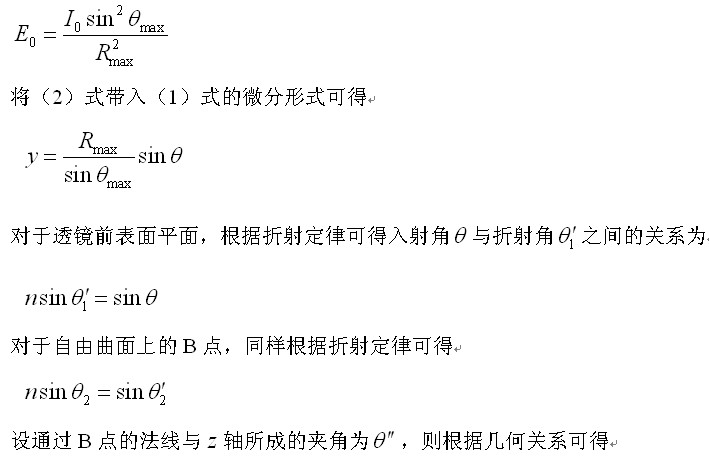
Let the LED chip light source be a Lambertian distribution, the spatial light intensity distribution is, then the axial direction light intensity is, the target light field illumination distribution function is the differential form of the solid angle element. Ideally, the lens has no absorption, no reflection and scattering, and the luminous flux emitted by the solid angle of the light source corresponding to the cone angle is equal to the luminous flux received within the corresponding radius of the target illumination surface, and the energy balance equation is

It is assumed that the purpose of the LED lens design is to require the illumination of each point on the target screen after the light passes through the lens to be a certain value, that is, the illumination of the target illumination surface is uniform. Considering that a certain solid angle of the light must correspond to the area distribution of a certain target illumination surface, when the angle of the light exit is the largest, the position coordinate of the light on the target illumination surface is, and (1) the boundary condition is obtained.


This is determined by equation (12).
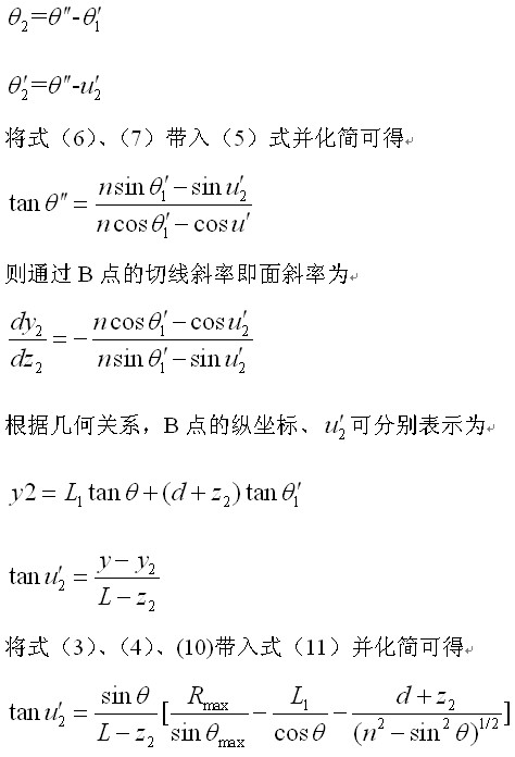
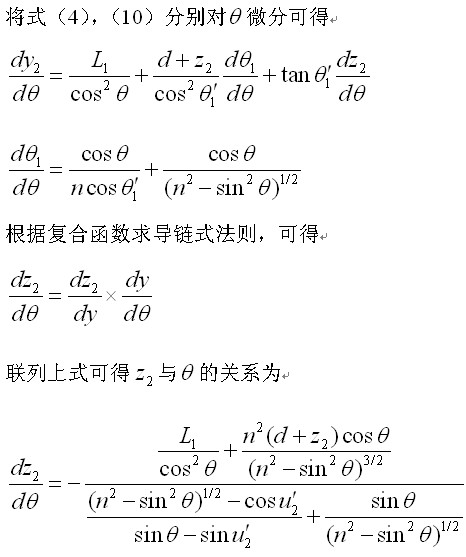
It can be seen from the formula (16) that, in a one-to-one correspondence with a certain angle, a uniform spot having a radius can be obtained on a target illumination surface at a certain distance. Equation (16) is a relatively complex differential equation. In order to obtain the data set of the function, according to the initial conditions and other parameters, as the independent variable, the fourth-order Runge-Kutta method can be used to solve some columns, , ,..., and the corresponding values, obtain the corresponding values by equation (10), obtain a series of data points, fit them into B-spline curves in CAE 3D software, and then import them into optical simulation software and import them into the model. Give optical properties, and finally use Monte Carlo non-sequence ray pursuit.
3 design examples
The non-sequence ray tracing software Tracepro based on Monte Carlo method was used to model the illumination effect of the receiving surface. Optical simulation tracing software Tracepro is a commercial optical software based on ACIS Solid Modeling Kernel developed by Lambda Research Corporation. It is widely used in lens design, backlight design, LED lighting design simulation and so on. Tracepro uses universal ray tracing techniques to trace light. This technique allows the operator to introduce light into the constructed model. At the intersection of the light and the model, individual rays follow absorption, reflection, refraction, and diffraction according to surface properties. And the law of scattering, so as to obtain the optical distribution of the entire space. The general process of building an optical model with Tracepro and simulating the calculations is to create a geometric model, set the optical material, define the source parameters, trace the ray, and analyze the simulation results.
The optical analog part adopts a high-power LED chip with an area, the light effect is set to the total luminous flux, and the remaining parameters are: the distance between the light source and the front surface of the lens, the thickness of the lens, the projection distance, and the radius of the target illumination surface is set. , . BK7 glass is selected from the material of the curved lens, and the refractive index of the material. Using matlab numerical calculation software to solve the differential equation (16) parallel column correlation equation can obtain a series of coordinate data about the discrete surface of the free-form surface, as shown in Figure 2. These data points are imported into the 3D mechanical modeling software PROE and fitted to a smooth curve by B-spline curve. Finally, the curve is rotated 360 degrees around the optical axis to obtain the solid model of the free-form lens. The lens model The outer surface is the free surface we are looking for. Since the maximum value calculated by matlab is, and the initial lens thickness is set, the cylindrical model to be stretched on the front surface can meet the needs of the actual model. The outline of the whole model is shown in Fig. 3.


Save the free-form model generated by PROE as a format file recognized by the optical simulation software Tracepro, and import it into Tracepro. After setting the light source properties, material properties, and acceptance surface properties, start to trace with 1 million rays. Finally, The illuminance distribution map is shown in Figures 4(a) and (b). It can be seen from this figure that the designed free-form lens better achieves the collimation of light. As can be seen from the illumination distribution map (Fig. 4(a), at a projection distance of 20 meters, the uniformity of illumination in a circular receiving surface with a radius of 650 mm can reach 92% or more (uniformity is defined as the minimum illumination of the entire region). The ratio of the average illuminance to the entire area); and from the illuminance distribution of the area coordinate system in Fig. 4(b), it can be seen that in the horizontal direction and the vertical direction, the surface is received in the range of -650mm to 650mm. The illuminance is basically the same, approximating the maximum illuminance over the entire illuminated surface. Outside of this range, the illuminance drops rapidly. The percentage of energy received by the receiving surface at 1000 mm x 1000 mm and the energy emitted by the light source was 86.18%. According to the principle of equal illumination, the theoretical illumination uniformity should reach 100%, but it can be clearly seen from Fig. 4(b) that the illuminance value decreases not at a right angle but at a steep angle outside the range of 650 mm from the center point. The slope is decreased. The difference between the two is mainly due to the assumption that the LED light source is a point source, and the optical simulation uses an area of 1 mm × 1 mm. Therefore, the results obtained from the point source theory are in a certain deviation from the actual situation; There are also some errors in the production of smooth surfaces by finite discrete point fitting. The reason why the energy utilization rate is small is that as an extended light source, light emitted from the off-center light-emitting surface does not fall on the target surface after entering the refractor, thereby causing energy loss.


Figures (5) and (6) show the distribution of the received illuminance and energy utilization at different projection distances. The relationship between the area of the receiving surface and the projection distance at different projection distances is: where is the side length of the square receiving surface, which is the projection distance. Because the receiving surface area is different under different projection distances, the illuminance distribution point on the minimum receiving surface is processed as follows: the ratio of the illuminance distribution distance on the minimum illumination receiving surface is multiplied by the maximum projection distance and the minimum projection distance as the illuminance distribution. The distance and illuminance distribution are normalized, and the relevant tests verify that the weighting method is consistent with the actual situation and does not change the uniform distribution of the original illuminance distribution. The illuminance distribution of the remaining receiving surfaces is also treated as described above. It can be clearly seen from Fig. 5 that the illuminance distribution at different receiving surfaces is basically the same when the projection distance is changed from 10 m to 90 m, indicating that the system performs a better collimation of the light beam. The basic control is in the range of 4° angle. It can be seen from Fig. 6 that, in the case where the projection distance becomes large, the energy utilization rate slightly decreases, but the magnitude of the decrease is very small, and the overall energy utilization rate is not substantially affected.


4 Conclusion
According to the analysis of the illuminating characteristics of the LED light source and the illumination requirements of a given target surface, according to the energy conservation and the law of light refraction, the general equation for achieving the collimated uniform illumination refractor is obtained. The Matlab numerical calculation software, PROE three-dimensional modeling software and Tracepro optical simulation software performed ray tracing on the refractor model. The results show that uniform collimation illumination can be achieved with only a single refractor, and the uniformity of the target illumination surface is more than 92%. At the same time, the function of illuminance distribution on the target illumination surface is basically unchanged under different projection distances, and the energy utilization rate remains basically unchanged. This design can be used in places where a collimated beam is required, such as a flashlight for a flashlight, port or dock.
Envoyer à ce fournisseur

Privacy statement: Your privacy is very important to Us. Our company promises not to disclose your personal information to any external company with out your explicit permission.

Fill in more information so that we can get in touch with you faster
Privacy statement: Your privacy is very important to Us. Our company promises not to disclose your personal information to any external company with out your explicit permission.